Squeezy Crush
Slips are great. (No, not what you wear under you skirt to keep it from riding up, the handling tools that hold your pipe in the rotary table. Sheesh.)
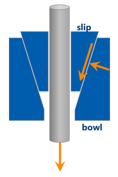
It’s really a simple machine, a basic wedge (well, a cone actually, because it goes all the way around, but I’m going to stick with “wedge” because I haven’t had enough coffee yet to screw around in another dimension) that we set into a slip bowl with a matching taper. When you set the slips around your pipe, the teeth of the slip dies bite into the tube, the pipe and slips start sliding downward, which causes the wedge to kick in and grip the pipe tighter. A little basic geometry, and slips keep you from dropping crap in the hole. Yay, slips!
But … the wedge has a downside. This is more than a hearty hug—it throttles the tube, applying transverse force to our poor drill pipe. That sidelong stress combines with the tension that’s already there in a bad way, activating the ugly side of Dr Von Mises. So the same slips that keep you from dropping your pipe in the hole might also break your pipe, causing part of it to drop in the hole. (Or shoot out into the Gulf of Mexico. It’s happened.)
We need to know how much is too much: how much weight can we hang off the pipe in the slips before they do their best anaconda impression? I’m going to call that the “slip crushing capacity,” because it’s just like tensile capacity or torsion capacity—it’s the amount of load your pipe can carry before it breaks.
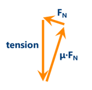
It seems like we could calculate such a thing … here, let’s give it a shot. We’ve got the force vectors adding up such like:
Hm, there’s some trig and algebra there, but I have every confidence you can figure it out. That then gives us the amount of transverse force being applied to the pipe. That force has to spread out over an area … dangit, I need to deal with a third dimension after all.
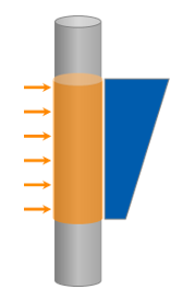
So we take the total transverse force and divide that by the “contact area” that goes around the pipe. That is an applied external pressure, and my friend and yours, Gabriel Lamé, has us covered for the hoop stresses due to the transverse force. Add that (well, like, combine it using Ricky von Mises’s distortion criterion) to the axial stresses we already know about because of hanging weight, and we find the load at which something gives. (The ID fiber is the something that giveth, by the way.)
Three things. First, in the interest of giving credit, Reinhold & Spiri did all that math way back in 1959 in a seminal World Oil article, so don’t go blaming it on me.
Second, you might notice a backwards “y” in the vector triangle up there (it’s a Greek letter “mu,” which you would know if you were cultured). That stands for the coefficient of friction, and we don’t know what it is.
This happens a lot, in fact—friction is rarely quite as simple as our block-on-an-inclined-plane problems from high school physics. The temperature, the cleanliness, the contact area, the wear and tear, all of it makes a difference in the way your surfaces are going to slide. As such, we generally have no idea what the effective, operational coefficient of friction is on the back of our slips.
Here's what I says: use 0.158.
Random—lemme ’splain. T H Hill has been involved for a looong time on deepwater Gulf of Mexico landing strings, the kind of heavy lifts where “failure” is something like “we drop our unfishably-heavy casing string into our tens-of-millions-of-dollars well and then probably deal with well control issues before the government boats start to show up.” That makes you … cautious, and operators like to call in some backup (us) for that.
Probably 25 years ago now one customer called us because they’d had a slip crushing failure. We looked at their calculations, and realized they’d used a coefficient of friction of something like 0.25. That’s less conservative than our 0.158—higher, stickier friction numbers lead to less squeeze, increasing the slip crushing capacity, and vice versa. They calculated that the load would be ok, and it wasn’t. Data point number one.
We use a coefficient of friction of 0.158. (I know, that’s an odd choice, but it’s actually the friction that gives you a ratio between the tensile force and transverse force of 3.0 on API slips which have a taper angle of 9.46°. Do the algebra, you’ll see it.) We calculated that they would, in fact, have the failure that they had. (Too late, of course, but still.)
We’ve used that 0.158 number for basically ever. T H Hill has never had a failure we would not have predicted with our slip crushing capacity calculation using the Reinhold-Spiri formula with 0.158 plugged in for friction. In 30+ years.
How many data points was I up to? Oh, right. One.
Look, I’m not saying our calculation is perfect; I know full well it’s not. I’m saying, with all that no-breaky experience under our belts, we’re at least being conservative. You might be leaving some extra capacity on the table, but when we run our Excel calculator, I’m fairly confident that you are not going to have a failure due to the pipe being overloaded in the slips.
That was number 2. Now for thing number 3 (it’s a doozy).
That Reinhold-Spiri formula is all manner of wrong. Look at it! It assumes the transverse force is spread evenly over the contact area! It assumes the contact area goes all the way around, but there are gaps between the slips! It says the transverse force of big, pointy teeth is the same thing as even external pressure! It’s just dumb!
Since it’s so clearly wrong, people have tried a few other things. One of my favorite examples was a study to apply vertical line loads to the pipe (representing the force from each slip) and use that to determine the stresses on the pipe. It was reasonable and elegant.
It also gave slip crushing capacities that were significantly less than the loads we apply with the slips every day, so … it didn’t really catch on.
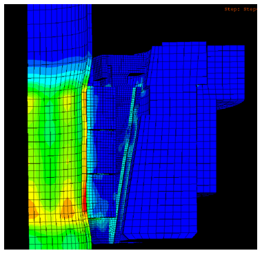
So if math doesn’t do it, let’s use computer modeling! (Which is also math.) I’ve seen and built very detailed models of slip crushing, with the slips and the pipe and the bowl and the whole shebang.
But that leads to a different issue: when does it fail? I know, I know, that seems like a dumb question (“breaking is failing, moron”), but FEA can tell us when a single point begins to yield. Is that ok? Probably; that one single point isn’t going to make much of a difference. Are two yielded points ok? 10? 100?
You begin to see the problem. When we’re doing analytical calculations for a whole cross section (like tensile capacity) or even a “fiber” (like torsion and bending), then yield = failure. But when you’ve got wild stress gradients over multiple small areas, defining how far is too far becomes a bit subjective.
“Subjective” then means “slip manufacturers start fudging the numbers to get higher ratings” which turns into “nobody trusts the FEA work” and “there’s an API committee concerned with this that has made basically no progress in the past decade.”
So.
Maybe forget the computers, you pointy-heads with all your fancy math-a-magic (says the company man to, well, me). Just put the thing in a test frame and pull on it! Then we’ll see how it actually works!
Eh, except we have the same problem. The pipe will begin to yield at some point, and we’ll have to determine how much is too much—slip crushing doesn’t go from “perfectly fine” to “shrapnel” all of a sudden. You put strain gauges on, but you see how small those hot spots are up in that FEA picture, don’t you? If you move the gauge by 1/4", you change the results by an order of magnitude. Oh, and tiny changes to the test setup will also dramatically change your test results (we’ve seen it), which calls into question how reflective of reality your test actually is.
Oh, my, it seems I’ve painted myself into quite a corner here—what shall I do? I already told you, 18 paragraphs ago. (Did you count? I’ll wait.) Just use the (wrong) Reinhold-Spiri equation, plug in 0.158 as your friction factor, and maybe use a safety factor for good measure. Probably conservative, but you’ll be ok.
Now for the complicated part.
“Wait, now comes the complicated part, Grant?!”
Yes, because now I’m not going to talk about the Excel spreadsheet you’re going to smugly send to all your colleagues. I’m talking about every day, dirty-hands work, making sure what your rig is doing isn’t going to hurt somebody or mess up your pipe.
Do you know what the original Reinhold-Spiri article is about? It’s not primarily about their equation; that’s back in an appendix. “Why Does Drill Pipe Fail in the Slip Area” discusses at length all the ways your slips can be the problem in messing up the tools you use every day. They talk about worn master bushings, worn rotary tables, worn slip bodies, worn and unevenly-replaced slip dies, setting the slips while the pipe is moving, catching the tool joints in the slips, using the slips to back up the tongs, riding the slips on the pipe …
You feel attacked yet? GOOD! Stop that!
Slips get used every day, over and over again, getting beat up and thrown around and generally forgotten about. The dies wear down, and they don’t grip the pipe as well anymore, so it starts to slide—you pay for the downgrade. You use them as tong backups and it cuts into your tubes, leading to fatigue & washouts—you pay for the NPT. You cheap out on doing an inspection and your “inspector” doesn’t even bother buffing the paint off before he does a half- … er … hearted MPI—you might hurt somebody.
The slips on the rig are easy to forget, but I beg, I entreat, I implore you to pay attention and have a maintenance plan. It will save you money, time, and heartache to take care of your handling systems.
And don’t even get me started on elevators …


