You Know What Happens When You Assume
Doncha hate overtorqued connections? The threads get all galled and deformed …
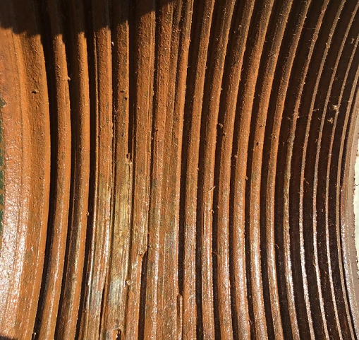
… the box counterbore gets smashed and destroyed …
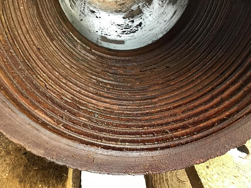
… the seal face yields into weird, unhelpful shapes …

Everything’s just generally boogered up, and that makes me haz a sad. So I need to find a way to make sure the torque I apply to my connection while I’m drilling is always less than the torsional capacity of that connection.
Wait, what’s the “torsional capacity” of a connection? There is a torque that you can apply to a connection at which something in the connection will start to plastically deform, and that’s non-good, and you want to avoid it. In almost every case, though, that’s not the “torsional capacity,” because even if a particular torque might work when properly applied, it don’t work if it’s applied downhole, with bending, and fluid flow, and vibrational hammering, and what-have-you. So we do our level best to keep all drilling torques below the makeup torque we applied at the surface.
How does one keep the drilling torque from exceeding our aforementioned makeup torque / torsional capacity? (Not by using words like “aforementioned,” sadly.) Well, the torque comes from the top drive, so let’s set the top drive so that it’s not allowed to apply more torque than the makeup torque.
|
You may be concerned that the top drive torque limit is only rigorously applied at the surface, and we want to keep all the torques all along the string below the limit. But since the friction in the well causes the torque to diminish on the way down, the surface torque is always the highest torque that the drill string ever sees. Except for this fun fact: those overtorqued-connection pictures I showed you up there? The top drive limit was set way lower than the makeup torque. It appears that I have made an incorrect assumption. |
Image 
|
Maybe some data will help. (Not that Data, though he probably could lend a hand.) We had a customer that, helpfully, decided to drill two wells that were almost perfectly identical. The drillstring design was the same, the trajectory was the same, the parameters were the same. In fact, there was really only one significant change:

Notice that, with Well A on the left, the torque plot looks like it’s gotten a haircut—the top is chopped off, first at 6-, then 7-, then 8 kft-lb. That’s the effect of the top drive torque limit kicking in; they kept bumping into the limit, and they incrementally increased the limit as they went. For Well B, the torque limit was higher (10 kft-lb), so the torque was allowed to grow its hair into a spiky purple mess.
To see why that one change makes a difference, let’s zoom in a bit. Right down there I’ve got the drilling data for one stand in Well A, and again you see that torque-limit cap in place (the blue line). But now it’s more obvious just how the top drive goes about following its torque-limiting orders. When the torque climbs up to hit the limit, the RPM dives down (pink line), slowing the rotation to avoid going over the torque limit. As the torque goes down, the RPMs can then speed back up to try to get to the set point (about 115 RPM in this case). The higher speed then causes the torque to climb back up (because absolutely nothing has changed about the physics of the drilling situation), which then causes the RPMs to go back down to avoid the torque limit … and so on.
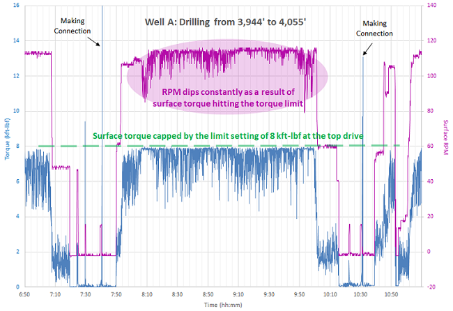
Ponder that for a moment: by setting your top drive torque limit low enough that the drilling torque bumps into it, your top drive is now pumping vibrational energy into the string.
|
Image 
|
I’m beginning to see where my assumptions went wrong. Saying “the torque is highest at the surface” is also saying “the string is in a steady-state with no vibration to it.” We’re used to having vibrational input at the bottom of the string—stick-slip is definitely real—but most of it is damped out by the time we get to the surface, so we ignore that particular time-based component. But when the stick-slip at the bottom causes erratic torque at the top, which is then “corrected” by the top drive pulsing even more vibration into the top … well, you can see how things might get a little sideways. |
(Which, by the way, is exactly what happened in Well A. They had breakout torques in the 45–60 kft-lb range, after setting the torque limit at 8 kft-lb, max. In Well B, that purple-haired punk got off scot-free, with no breakout issues.)
I got a chance to present this idea at the IADC/SPE conference in March. Dr Bill Zheng, Srinivasa Koneti, and I put a paper together that walks through the assumptions we typically make about our top drive limit, and how that can lead to some nasty failures. We (and by “we” I mean “Dr Bill”) even went through the process of solving the characteristic vibration equation:
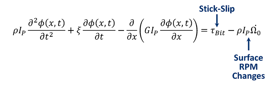
With the result that we can model what happens in certain cases, like when you suddenly and temporarily slow the rotation by 50 RPM at the surface:

(There’s a lot in that graph, but check out the bold black line. At first the RPM dip causes a brief left-handed torque dip, as you might expect. But pretty soon we’ve got torque waves bouncing all over the place, both negative—which would be decreases in the drilling torque seen—as well as positive increases over the steady-state drilling torque. The extra inertia down at the BHA—the dotted lines—causes things to flail around like the proverbial decapitated yardbird.)
But with all this danger of damaging torsional waves caused by a limiter that’s supposed to avoid damaging torsion, the answer is surprisingly simple: don’t bump into your limit. If you set the top drive torque high enough that regular drilling doesn’t get there, then the top drive spits out a nice, steady RPM and you can blithely pretend that your steady-state assumptions are true.
That, my friends, is the kind of engineering control I like: if the assumptions I’m making are wrong, I’ll change the world to match my assumptions. (I don’t always get to do it that way …)
