Oil & Gas
Buckling, or Don’t Be Scared
Mar. 10 2022
Buckling is something of a mystery to a lot of people in the drilling industry, and methinks this may be the reason:

That's not even the solution, that’s just the math problem you have to solve. Don’t worry, though, you don’t need to know how to do that. (Although don’t let me stop you; you can figure it out. Along the way there’s a fun Wikipedia hole to fall down, too, about the guy who wrote out the complete theory on how to solve polynomial equations like that the night before he died in a duel over a French girl. Seriously.)
See, the math associated with buckling is a bit, um, dense, but the concepts are really pretty easy to wrap our minds around. Here, let me have your mind for a minute, and I’ll start wrapping.
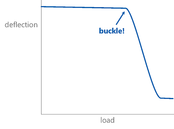
First, buckling—in a general sense—is when a load vs. deflection curve falls off a cliff. To start with, you apply load to something and it deforms a little bit. At some point, though, the load-carrying-thingy suddenly changes its shape due to the loads applied and a small amount of additional load will cause a large amount of additional deflection.
|
I've been using generic words like “deflection” and “load” because this could happen with wrinkled airplane skins, crushed beer cans, or collapsed casing, but we’re specifically interested in columns here (drill stem stuff with weight applied), so the load is compression, and the deflection is how much it squats down under that compression. At some point the middle of the column kicks out to the side, and the house comes crashing down. |
Image 
|
But what point is that, Grant? How much compression does it take to buckle our pipe? As is typical, it depends on who you ask.
Most people (well, most engineering dorks like me) would immediately think of Euler.
|
Image 
|
Good ol’ Leonhard figured out an equation in 1757 that would predict the critical load at which a column goes kaput. For our purposes (I’m assuming pinned ends) that load is: Image 
|
It depends heavily on the effective length of the column, which is something you might have guessed—long, skinny columns are floppy and easy to buckle. Leo did the math to prove it and, importantly, quantify it. For example, let’s imagine we have a short-ish length of drill pipe, something about 1,000 ft long.
I don’t really need to give you any more information, do I? If L = 1,000, L2 = 1,000,000, and it’s going to be hard to get a critical buckling load that’s not itty-bitty when you have to divide everything by a million.
That problem was recognized and highlighted by Dawson and Paslay in 1984—they used an example where the total ability of a 5" drill string to carry compression is about 29 lb. They also recognized that, at the time, people were applying way more compression than that without issues, so clearly something was missing.
What was missing? The wellbore, mainly. Leo’s column was vertical and floating in space when he did his work; our columns are usually going to be pushed into the wall of our well by gravity and/or curvature. Since the wall is a curved trough, buckling requires the pipe to climb up the wall away from the stable position, so pushing the pipe back down into the wall provides a remarkable amount of stability.

The equation developed by Rapier Dawson and Paul Paslay, then, says that we gain oodles of buckling capacity thanks to the stabilizing normal force:

I’d like to highlight something here: in a vertical well, the angle of the well (θ) is zero. The sine of zero is zero, so the critical buckling load in a vertical well according to Rapier is … zero.
Blink … blink.
It doesn’t matter if we’re talking about 2-3/8" tubing, 5" drill pipe, or flippin’ 12" drill collars, Paul insists that the capacity of any component to carry compressive load when it is oriented vertically is precisely zilch.
But …

… um …

… er …

… it seems like columns do okay, yeah? Holding up stuff vertically, under compression, for literally thousands of years?
And yet, here go Dawson and Paslay saying that our vertical drill stem elements have no capacity for compression at all. Why on earth would they say something so dumb? And (maybe more important) why would we listen to these madmen?
I mentioned it before; in the Euler column buckling world, the length of the column (or “slenderness ratio” if you’re comparing the length to the bending resistance) is the driving factor. Since our columns are really long even when they’re pretty hefty—5 inches this way, but 10,000 feet that way—Dawson and Paslay just assumed an infinitely long column in their derivation. Presuming an eternally long and floppy drill string, now you get why the answer in a vertical well is always zero. And honestly, that answer is always wrong, but it’s not very wrong (remember 29 pounds for 5" drill pipe?) and it’s conservative and it’s way easier to not have to mess with effective lengths. So Dawson and Paslay get the nod (sorry Leo).
Alright, so we use the Dawson and Paslay equation to calculate the amount of compression that our pipe can carry before it buckles. It’s pretty straightforward, and I can turn it into a pretty graph to make it even easier to use.

But time marches on, and a problem was found with Rapier’s work. The basic idea was quite sound—normal force pushes pipe into the wellbore wall, developing a significant amount of buckling resistance. The problem is the equation says that normal force equals the sine component of the weight.

That’s fine on your typical high-school-physics-style inclined plane. But what if it’s a curve?

The fact that you’re pushing the pipe into a curve means that, in a build section, you’re pushing the pipe into the wall an extra amount because of the curvature. Rapier & Paul ignore that effect, but in a building wellbore it simply adds extra normal force, increasing the buckling capacity. You usually have to be trying to get pipe to buckle in a build section.
However, a drop section is not so easy. There’s still a curvature effect, but whether it helps or hurts depends on the location of the pipe, i.e. whether it’s on the top side or the bottom side of the well. On the bottom of the well the curvature effect is trying to lift the pipe up, decreasing the normal force and the buckling capacity. On the top of the well it’s like an upside down build section, so the curvature effect increases the pipe’s stability.

Ok, so is the pipe on the top or the bottom? Well, imagine you take your pipe and just strap it down on one end to a big table. (No, I don’t know where you’re going to get a table that big, we’re doing this in our mind.) It’s going to sag at the other end by an amount that depends on the particular weight and stiffness of that pipe. So that downward curvature that it follows is sort of its “natural drop rate.” (I’m just using that as an analogy here; don’t take it too far without some massive qualification.)
We then compare the “natural drop rate” and the actual wellbore drop rate: if the well is dropping more slowly than the pipe wants to, then the pipe falls to the bottom of the well and is supported by the wellbore. If the well is dropping more quickly than the pipe wants to, then the pipe is pushed downward by the well and the pipe runs along the top side of the wellbore.

Calculating and keeping track of all of that is no mean feat. Luckily that’s exactly what He and Kyllingstad did for us in 1993. They were the ones that put together the equation I frightened you with at the beginning of this article, the one that Galois knows how to solve. But that’s the point of this article: the math can be a little frightening, but it’s already done for you.
Tom Hill (yes, the founder of T H Hill Associates, the company that hired me way back before iPhones existed) and Brett Chandler wrote another paper in ’98 with the express purpose of taking the complicated He and Kyllingstad formulations and reducing them to a curve you could use in the doghouse at your rig. Those curves, along with Dawson and Paslay curves for when your wellbore is straight, got printed in DS-1 Volume 2 for easy reference and access.

So don’t be scared of buckling; other intrepid pioneers have blazed the trail for us. And don’t be scared of math, either. (Although make sure you don’t get shot in a duel.)
